1.3-ICT 1900 Range Architecture
The ICT 1900 compatible range relied on two key components to achieve its aims of hardware modularity and program portability.
The ICT Standard Interface, specified by ICT and RCA, besides providing enhanceability and flexibility to the customer, had the additional benefit of establishing a “firewall” between processor design and peripheral design, and made it very much easier to manage interfaces between development elements.
The 1900
Executive, already present in the FP6000 architecture, was used by the ICT
designers to maintain across all processors a tight and comprehensive compatible programme interface that was
strictly controlled, and maintained by the “Compatibility Committee”.
Additionally, Executives provided basic features for loading and running jobs, thus allowing 1900 machines to be delivered without Operating Systems (This gave ICT a competitive advantage in early deliveries at a time when Operating Systems complexity, development costs and timescales had been underestimated by most computer manufacturers).
1.3.1 – System Architecture
(Based on the talk given by Charlie Portman at
the
System
Diagram
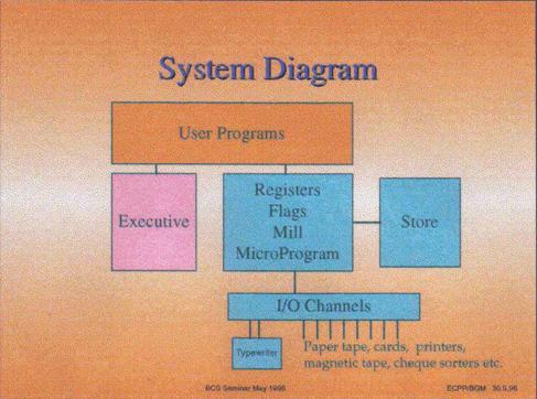
The above diagram shows the main components of the system and the relationships between them.
A user program sees instructions, which individually are executed by either the processor hardware or by executive. The user need not be aware of whether a particular instruction is carried out by hardware or Executive, and indeed it may well be implemented differently on different machines in the Range (or on different releases of the same machine). The instructions implemented by Executive are known as ‘Extracodes’. When the hardware detects an instruction that needs to be carried out by Executive, it interrupts the flow of the program and transfers control to the Executive routines. When Executive has performed the required operation, control is returned to the user program at the instruction after the one that caused the interruption.
A peripheral input/output instruction is always carried out by Executive, which initiates the required operation and then returns to the program whilst the actual I/O takes place. At the end of the I/O operation the peripheral raises a Program Interrupt request, which causes the currently running program to be interrupted (which incidentally may not be the one that requested that I/O) and Executive to be entered to carry out final housekeeping, including signalling to the requesting program that the operation has completed. Control is then returned to the interrupted program.
Word
Formats
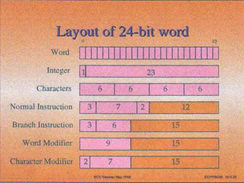
The RAM (which at that time was mainly core store) held 24 bit words, with a 25th parity bit. The Bits of the word were numbered from the MOST significant end 0 to 23. A word could contain different types of information, the most important of which are shown in the above diagram and are a signed integer, up to 4 six-bit characters, program instructions, and word or character modifiers. For integers 2s complement arithmetic was used, so an integer had the top bit - bit 0 - treated as 'worth' minus two to the twenty third power. Fractions, mixed numbers, floating point and multilength numbers were also defined.
Note particularly the lengths of the N fields (shaded orange in this figure).
Program
environment
The user program saw a consecutive set of 24-bit words numbered from 0 upward. Words 0-7 were known as the accumulators , which were addressable by the X field of an instruction. Words 1,2 and 3 could also act as modifiers addressable by the M field of an instruction (0 in the M field indicating no modifier). The contents of the modifier register were added to the N field to produce the required address. There was a maximum unmodified address of 4095 as there are only 12 N bits (except in jump instructions which have 15 N bits), from which it follows that the last directly addressable data word is in location 4095 (and the last instruction possible is in 32767). Using address modification the modified address was of 15 bits, and hence addresses up to 32767 could hold data provided it was accessed via modified instructions. The other field in a modifier was a counter, which could be used in certain instructions to increment the N field and count down, and thereby facilitating access to a set of consecutive addresses
The function bits were decoded to select the usual functions such as copy, clear, add, subtract, shift etc.. Jumps with testing of the carry, sign and overflow of the last operation, unconditional jumps, and counter / modifier jumps were also provided. Counter/modifier jumps incremented the modifier, decremented the counter and jumped if the counter was then zero; they were used to generate a program loop which progressed through an area of store defined by the starting address and the counter value.
Further functionality through a set of Extracodes which behaved, to the object program, exactly like hardware implemented instructions performed operations such as assigning peripherals, performing data transfers and sending messages to the operator. These extracodes were assigned normal function numbers, which the hardware turned into an interrupt into the Executive program. In some cases instructions that were carried out by hardware on the larger machines in the Range were implemented as an Executive Extracodes on the smaller systems (multiply and divide were done in this way on the 1902 and 1903 for example). When an extracode was encountered the user program was suspended, and its order number (the address of the current instruction) and flags (overflow, carry etc.) were dumped in word 8 of its own core store area, and control was transferred to Executive's entry point. Executive mode was set on entry which extended the hardware order code to allow executive direct hardware control over the peripherals, datum and limit registers etc.
Multi-programming
and Protection
Because the machine was intended to run several user programs 'concurrently' it was necessary to provide a means of ensuring that the programs did not interfere with each other (nor with Executive) regardless of which programs they were or in which order they were loaded. This was achieved by adding a datum to each (modified) address and checking that the result did not exceed a limit defined by the declared program size. This process was carried out for every execution of every instruction, using additional hardware, the reservation checker, to keep the speed penalty down. Provided that Executive allocated each program a unique area of store delimited by the datum and limit registers there was no possibility of one program interfering with the store of another program, or Executive. Executive itself ran with a datum of zero and no limit, so the Executive code had to be 'trusted'.
The datum and limit mechanism means that programs were operating in a virtual environment (addresses are relative to the datum not to real store address zero). This means that they could easily be moved in the core store, which is a necessary requirement for multiprogramming store management. When a program was moved it was only necessary to adjust the datum register accordingly and the program could continue unchanged.
The other possible area of interference between programs would be through the peripherals. These were allocated to programs (on request) by Executive and assigned to symbolic channel identifiers so that the program need not know which particular device it was using. Of course, Executive would not allocate the same device to two programs! In addition Executive ensured that the area of store into/from which a program requested data transfer, was within that program’s allocated region, and it set the hardware register that controlled the actual I/O transfer. The actual data transfers were done by a hardware mechanism called the Hesitation System. When a peripheral was ready to transfer a character (or word), it raised a hesitation request line, which caused the hardware to briefly hesitate from processing an instruction to allow the special hesitation hardware to steal a store cycle to transfer the character (word) into the area designated by Executive.
Peripherals were attached to each processor via the ICT (later ICL) Standard Interface. This meant that any peripheral could be attached to any member of the 1900 Range, and all peripherals had a generic similarity which simplified Executive and peripheral design. The use of the Standard Interface also meant that a particular customer could upgrade his central processor to a higher member of the Range and at the same time keep all his existing peripherals.
Extended Addressing
An early enhancement of major significance was removing the 15 bit addressing limitations imposed by the original bit assignment of the instruction word. Core stores of 16k words/module were already available and larger modules were promised imminently. This change was achieved by adding the Extended Addressing and Extended Branch modes to the architecture. These allowed 22 bit addresses through modification and indirection. Hence, in theory, core storage of up to 4 million words (16 mega characters) could be used by a user program.